by Chris Hannon
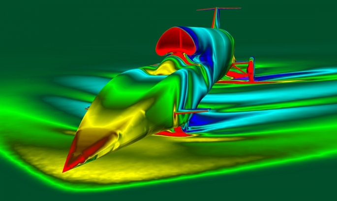
Computational Fluid Dynamics is the calculation of the behaviour of a fluid, such as air. It calculates things like velocity, pressure and density, all using high performance computers. As no supersonic wind tunnels with moving roads exist, it is much cheaper to use CFD to design the external shape of Bloodhound. The picture on the right looks rather stunning, but is bad news aerodynamically - the colours indicate big changes of pressure all over the car!
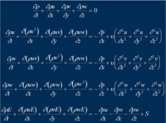 We have to solve Navier-Stokes equations (left) which are governing equations for viscous, compressible fluid flow. They are partial differential equations describing the density, velocity and pressure in the flow.
They are solved numerically, i.e. We get results for the car at one speed, one steering angle, one temperature, etc. This acts as a snapshot of what the car is doing; we then do take multiple snapshots and plot the results to see the behaviour of the car. Even when using the Intel super computer, it still takes 2 or 3 days for each snapshot to be calculated, so we have to think ahead how few snapshots can be used to determine how to design the car.
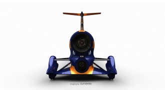 This picture on the right is of Config9. It had unacceptable aerodynamic performance, with large values of lift and downforce being generated across the speed range.
A “Design of Experiments” was used to define some of the key variables at the rear of the car to reduce the change in lift during a run. I’ve highlighted here some of the most sensitive variables which led to geometry changes in Config10, which is the show car below.
The lower suspension acts like a wing, so inclining it upwards gives lift and downwards gives downforce
A boat tail angle was added to control where the air separates from the rear of the car
A slab sided body (spam shape) was used rather than a pinched waist as this gave a more constant value of lift across the speed range
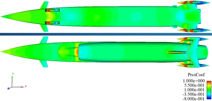
The result of the DoE is shown above. These are pressure plots of the top and bottom of Config10 at 1,000mph. Almost all of the car is the same colour, meaning the car is not trying to fly or bury its head in the desert!
 Airbrakes will be used to slow down Bloodhound. Their design is now reasonably mature as we are confident they will generate enough drag to slow the car satisfactorily.
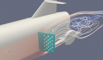
Here is a plot showing a vertical sliver of airflow through the airbrakes. We’ve added holes to increase the frequency of the flow behind the airbrake, which means their deployment is less likely to fatigue the rear of the car or damage the fairings around the rear wheel.
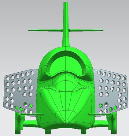
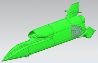
Here are a couple more CAD images of the current design of the airbrake.
We’ve removed the corners from the airbrake to increase the stiffness and left a solid chunk of material in the centre for the actuator to attach to the airbrake.
It is very challenging to model the flow around the airbrake, as it is a lot more complicated than modelling the flow around a streamlined body. The flow is unsteady, which means that our previous assumptions used to solve the model at one instance in time is no longer valid.
 What needed to be done was to run an unsteady model, which takes multiple snapshots of the airflow, with each snapshot being based on the results from the previous one.
This requires a lot of computer time and would have taken about 3 months if we used the full car model.
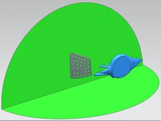 What we did was to use a simplified model of the airbrake and the wheel behind it (right).
This simplified model took around a week to solve and gave us a more accurate prediction of the drag generated by the airbrakes, as well as giving us an approximation of the frequencies of the flow around the car, so we know roughly how stiff the airbrake and rear structure needs to be in order to avoid those frequencies, which might otherwise resonate and shake themselves to bits!
The fin size has increased by around 70% compared with the fin on Config10. The vertical fin is there to passively steer the car back to zero steering angle, so that Andy hopefully won’t turn in circles.
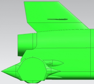 For the fin to be effective, we need a large surface area as far behind the Centre of Gravity of the car as possible . As the CoG has been moving backwards recently, and given the fin was already very close to the back of the car, we’ve had to switch to a larger fin.
We’ve been looking at the loads generated by this fin when the car is turning quite aggressively, as we want to be sure that the side loads on the fin aren’t enough to tip the car over, as that would be a very bad safety scenario.
Another Design of Experiments to fix the rear shape of the car will need to be performed next year, as the shape of the car at the rear has changed quite a bit compared with Config10.
We will also be adding extra fairings used to shield the movement of the suspension rods where they meet the body of the car. Previous models have simply had the suspension in the neutral position, whereas in reality the wheels will be moving up and down quite a bit, so we need to be sure this won’t cause any problems.