by Ben Evans
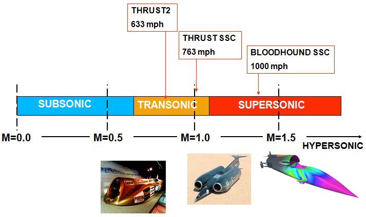
Thrust2 and ThrustSSC were very successful cars - ThrustSSC went faster that the speed of sound in 1997, but only just! BLOODHOUND SSC is designed to go well into the supersonic region:
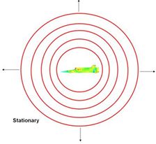
 When BLOODHOUND SSC is stationary, sound waves leave the car at equal speeds in all directions (see diagram left).
As the speed of the car increases (diagram right), the sound waves in front of the car (which are still travelling at the speed of sound relative to the stationary position) begin to get squashed up. This results in the frequency of the sound in front of the car being higher than behind - this is the "Doppler Shift" that we hear as speeding vehicles go past us.

 At Mach 1 (diagram left), the car is travelling at the same speed as the sound - the sound waves build up at the front of the car and form a shock wave.
When the car is supersonic (diagram right), the sound waves are left behind and form a cone of shock waves. Mathematics can easily give us the angle of this cone for any given Mach number.
We use a technique called Computational Fluid Dynamics (or CFD for short) to calculate where the shock waves form around the body of the car, and hence work out where all the areas of high and low pressure are (for more about CFD, see the page in the car section of the website here). By analysing the results, we get an accurate prediction of how much downforce or lift results on each part of the car.
Over the last few months, the design of the car has been refined and refined. Each change has to be checked out at Swansea University using CFD to make sure the aerodynamics are good. Until recently, each change has taken hours of computer time to analyse, but now, we are in the fortunate position of being able to use the latest and fastest computers and processing times have drastically reduced. That means we can look at a lot more variations and have great confidence in our design.
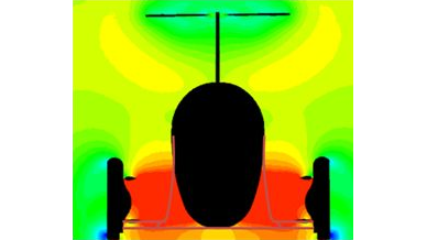
The diagrams below show different cross-sections of the rear wheel area of "config 6c" at Mach 1.3 - as always on these diagrams, blue is low pressure and red is high pressure.
 Because we are able to analyse shape so much faster, we can even look at using slightly different shapes and "what ifs" - the diagram below compares and early shape (config 5) with a new idea of swapping the jet and rocket engines around in order to get the car narrower at the bottom (config 8). The idea of this is to reduce the area where the high pressure waves build up and create unwanted lift. Also, different configurations of fins and tail can be compared.

Another variation we are looking at is different ride heights, again with the idea of reducing the amount of space that high pressure can build up.
Our very latest thinking has picked the best bits from all these different configurations, and added low rear delta-wing style struts (see diagram below). This looks very promising indeed!
