by Ben Evans, Swansea University
Well, this is it, we have arrived, after almost 3 years of tireless design evolution at the shape that we believe can take us to 1,000mph – from my perspective this does indeed feel like discovering the Holy Grail. Those of you who have been studying each configuration in our design journey will have become familiar with the ‘spot the difference’ game that seems to take place with each new vehicle shape. In this article, I aim to guide you through the key aspects that have made ‘all the difference’.
 As I’m sure you will be aware if you have been following the project, nearly all of our aerodynamic headaches over the last year have been focussed on the rear of the vehicle. The problem, in essence, was the huge variation in vertical load that the rear of the car was generating (of course in computational model terms) over the speed (Mach) range. Recall that one of the key objectives for the aerodynamic design of BLOODHOUND SSC has been Mach number insensitivity i.e. we have been aiming for a vehicle shape that delivers as uniform an aerodynamic characteristic as possible from subsonic speeds, through the transonic regime, and up to the supersonic target speed of 1,000mph. However, some of the previous configurations have shown to be generating significant downforce at Mach 0.5 and in excess of 10 tons of lift at the rear at 1,000mph i.e. far from Mach number insensitive! And all the more unacceptable when you bear in mind that the unladen weight of the car is not far off 5 tons!
So what has been going on!? Well we have to think about what happens to air flowing around the sides of the car at high speed. Above approximately Mach 0.3 (a third of the speed of sound, or roughly 200mph) air begins to take on the important property of compressibility. This means that air can not only change direction to navigate around an obstacle, but it can now also ‘squeeze’ or compress to help it on its way. The extent to which this compression (and associated density rise) occurs depends upon the speed of the air relative to the speed of sound and the shape of the object it is trying to make its way around (the reason BLOODHOUND SSC is long and thin is to try and reduce the extent of this compression as this usually translates into drag). The ultimate expression of air compression is a shock wave, within which this compression occurs almost instantaneously and manifests itself in the ‘BOOM’ and the beautiful pictures you might well have seen of the THRUST SSC shockwave on Black Rock desert in 1997.
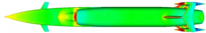 |
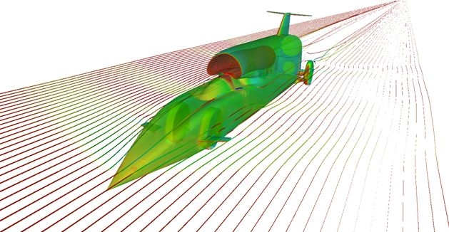
| Above: BLOODHOUND SSC config10 top – note long and slender to minimise air compression and hence drag, the colouring here is pressure distribution (at Mach 1.3) with reds indicating regions of high pressure and blues indicating regions of low pressure with intermediate pressures following the spectrum of colours in between |
Now imagine yourself as an innocent particle of air in the path of BLOODHOUND SSC travelling towards you at 1,000 mph (roughly 1.3 times the speed of sound). First of all you will have to navigate around the nose of the car by squeezing/compressing/slowing down through a shock wave (the bow shock on the car). Once you have successfully avoided the nose, you can then, briefly, accelerate down the side of the car until you meet air coming at you from above the cockpit canopy that itself has had to ‘shock’ and squeeze past the canopy and upcoming intake duct. This has caused you to have to change path, compress again in a shock wave and slow down. You have now survived this second interruption to your day and you are given the opportunity to accelerate down the side of the rear half of the vehicle until something rather ominous approaches you – one of the rear wheels! Just when you thought you were home and dry, you have to experience a third shock, which turns out to be the strongest shock of all. The density of the air through this shock wave almost doubles, and it is this that gives rise to deep red (high pressure) colouring on the front of the rear wheel fairings and also the source of our huge rear supersonic lift.
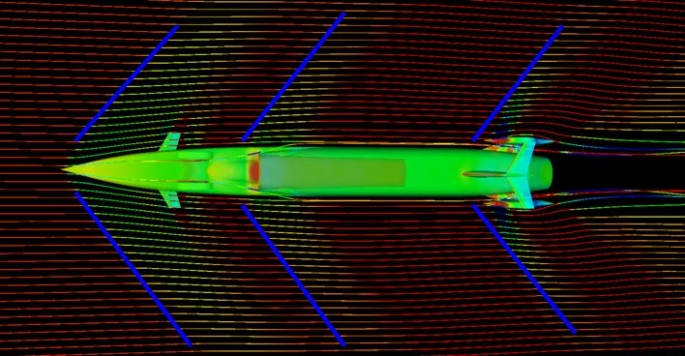 |
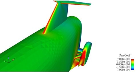
| Above: Velocity-coloured streamlines flowing around config10 at Mach 1.3 and indications of the main shock positions (red indicates high velocity and blue indicates low velocity, with intermediate velocities following the spectrum of colours in between). The car body is, again, coloured by pressure coefficient |
So, much of our time over the last year or so has been associated with managing the position and strength of this rear wheel shock system and its associated ‘high pressure cushion’ which has been acting under the rear of the car body causing it to lift.
Study Parameters:
 delta leading edge sweep angle
- base area
- rear wheel track
- fairing spike length
- fairing spike height
- boat-tail angle
- body-delta angle
- ride height
- delta angle of attack
- delta strut camber
- 'spam' shape
- diffuser
- suspension 'blister'
- delta leading edge 'crank'
- delta-body blend
- fairing radius
- fairing cone diameter
- delta angle of attack
 delta leading edge sweep angle
It soon became apparent that understanding the complex interactions between the positions and sizing of all of the components comprising the rear wheel suspension system and how they affect the strength and position of the rear wheel shock waves was not going to be an easy task. We therefore set about trying to simplify and parameterise the geometry at the rear of the car focussing on the variations that we felt were the critical ones: rear wheel track, position of the delta leading edge for example. Under the guidance of friends at MathWorks (providers of the incredible maths software package MATLAB) we implemented a technique known as ‘Design of Experiments’, which is essentially a very clever way of learning lots about the design space of your problem to find optimum solutions i.e. in our case, what combination of the parameters we were varying would give us the minimum rear car lift and drag.
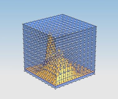 |
| Above: Discretisation of a 2-parameter design space in search for optima |
Ultimately, it is the output from this Design of Experiments study that has guided the way that the rear of BLOODHOUND SSC now looks. Importantly, it told us that we needed to minimise the rear wheel track width as far as possible (in our case, as far as we deemed it safe from a roll stability point of view) and also what precise shape the rear body of the car should take on and also the size and position of the crucial delta strut.
 |
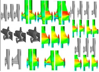
| Design of experiments optimised rear suspension geometry showing pressure coefficient distribution at Mach 1.3 |
What we have managed to do to remove the potentially show-stopping 10 tons of lift that we have seen previously is coordinate the positions of the rear wheels relative to the way in which the car body tapers in towards the base so that the shock wave generated ‘rests’ upon the top of the low delta strut. This delta strut effectively protects the underside body of the car from the high pressure cushion downstream of the shockwave and, in fact, generates significant downforce in doing so (n.b. the high pressure red on its top surface).
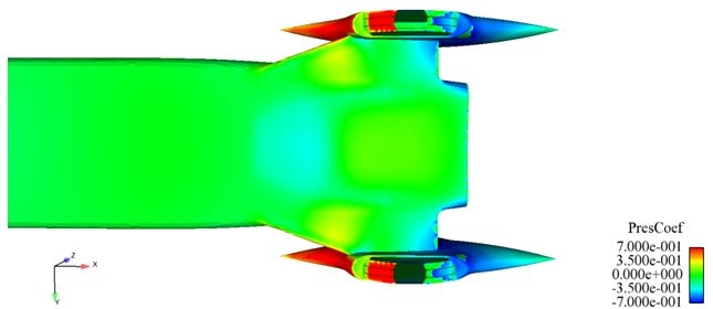 |
| Above: config10 underside pressure coefficient distribution at Mach 1.3 – note the almost entirely neutral green 0.0 pressure coefficient over the rear underside in comparison with the config9 equivalent |
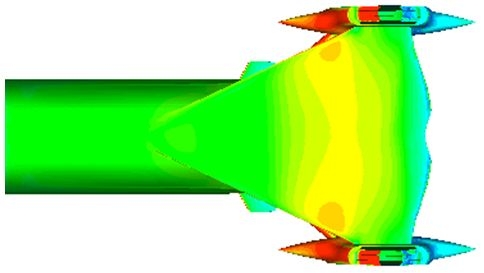 |
| Above: config9 underside pressure coefficient distribution at Mach 1.3 |
We are now in the position where the back end of the car is almost neutral in lift supersonic and generates a small amount of downforce subsonic. This is almost exactly what we were after when Ron Ayers set out his aero-objectives right back at the start of the project. Of course, there is a huge amount of relief that we have been able to fix this and we now turn our attention to the much easier job of getting the precise sizing of the winglets and fin right and also the exact position of the tip of the nose above the ground.
Unfortunately what this does mean, however, is that the ‘spot the difference’ game that lots of you have been playing throughout the design process is coming to an end! (at least as far as the external shape is concerned)