By Ron Ayers, (Aerodynamics and Performance)
 The shape of BLOODHOUND SSC is naturally attracting interest among designers and mathematicians. Several times I have been asked whether I have used optimisation techniques to create the minimum drag shape for the car. The questioner normally draws my attention to a mathematically optimised shape, or a mathematical optimisation technique, and seems surprised and disappointed to learn that I do not use it. Sadly, things are never quite so straight forward for a practical designer. In this Engineering Update, I answer this and other F.A.Q.s related to aerodynamics.
On BLOODHOUND SSC do you use the Sears-Haack body shape?
The Sears-Haack shape, derived from Area Rule mathematics, gives the minimum wave-drag in the transonic region for a body of given length and volume. The resulting shape is very slender, rather like a cigar, but with sharply pointed ends. Such a shape may be a mathematical optimum but is totally impractical for a supersonic car, as there are many other requirements that must also be satisfied. For instance:
1. Propulsion requirements dictate the use of a bluff rear-end to accommodate jet efflux or rocket efflux (in the case of BLOODHOUND SSC, jet efflux and rocket efflux).
2. A large intake is required to supply air to the jet engine, and smaller intakes are needed for other purposes such as cooling. These intakes have a big influence on the overall vehicle shape.
3. The driver wishes to see where he is going, so a forward-facing transparent surface is needed. The alternative idea, of replacing the forward facing canopy by a television display for a totally enclosed driver, is one we have rejected.
4. Wheels and suspension must be fitted.
5. A fin must be added to ensure yaw stability.
6. Controllable winglets must be added to ensure that the down-loads on the wheels stay within tightly-specified limits throughout the speed range.
7. The underside contours of the car may need modifying to ensure that the aerodynamic overpressures on the desert surface are not excessive. The shockwaves emanating from the underside of Thrust SSC were strong enough to destroy the desert surface, so the wheels were travelling through fluidised dust rather than on a solid surface.
It is clear that, by the time these requirements have been satisfied, the final shape bears little relationship to the optimum Sears-Haack body. And that is before drawing attention to the restrictions on the underlying theory that originally created the shape. Namely, that the optimisation purely minimises wave drag and ignores the influence of skin friction drag. Also, the Sears-Haack body is derived from the Area Rule, which specifically refers to the transonic region. BLOODHOUND SSC is, of course, interested in this region, but it must operate everywhere between M = 0 and M = 1.4, so optimising for specifically the transonic region is not necessarily helpful.
Despite this, can the Area Rule help?
The rule is helpful in that it introduces the concept of the longitudinal distribution of cross-sectional area. If we compute the c.s.a. distribution of our project and get a curve that looks as if it is from a multi-humped camel, then at any speed the drag is most certainly higher than it needs to be. Any smooth shape, even if not derived mathematically, will be better than a ‘lumpy’ one. And do not forget the space between the car and the ground. On most cars the top looks beautifully smooth, but this is wasted if the air passing underneath the car experiences an obstacle course through the suspension.
Do other optimisation techniques exist?
My attention has been drawn to some, but they are all undermined by the practical design considerations listed above.
Can you use self-optimisation programmes?
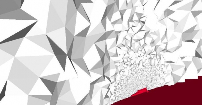
I believe ‘Solver’ routines do exist for CFD programmes, but defining the boundary conditions for our vehicle would be a nightmare. Also, our existing CFD model is huge. It requires a three-dimensional mesh of approaching 100 million space elements to define the volume around the car - see the picture at the top of the page, showing just a tiny part of the mesh, the small red object at the bottom is the car! Even using the enormous computer facility at our disposal, each run takes a long time. A self-optimising routine for such a complex model is outside our capabilities at this moment and probably will be for some time to come. It is conceivable that such optimisation techniques could be used to tackle local problems where these can be identified. I have in mind such things as wheel fairings or winglets. In all probability, time pressure will prevent us from even doing that.
So how do you proceed when designing the shape of the car?
On most aircraft or car projects (which are we?!) there exists a body of experience from previous similar projects. In the case of Bloodhound SSC there is no such ‘prior art’ to draw on. Even Thrust SSC was some 250 mph slower than our target speed, and other Land Speed Record cars were much slower even than that. However, experience is still a good starting point. Our senior CAD designers - Mark Chapman, Brian Coombs and Mike Turner, have all been involved in high speed vehicle design so instinctively know what shapes are likely to satisfy both the aerodynamic requirements and the practical constraints. Their CAD models are used by Ben Evans to create the CFD mesh so he can determine the aerodynamic forces on the resulting shape. After that, design is largely an iteration process.
No wind tunnel testing?
If someone would provide an enormous supersonic wind tunnel, complete with a ‘rolling road’ capable of 1000 mph we would be very interested, but no such facility exists.
What about rocket sledge testing?
We used this on Thrust SSC, specifically to check our CFD results. It confirmed that CFD gave good and reliable results at transonic/supersonic speeds and with small ground clearance. Having gained that confidence in CFD we have no reason to repeat the experiment.
Could Bloodhound SSC benefit from riblets?
Riblets are microgrooves, rather like deep scratches, arranged over the vehicle surface in a stream-wise direction. It has been found that they can reduce the drag of a vehicle by (according to one report I have seen) about 3% at subsonic speeds. Do they work at supersonic speeds? I have seen no evidence that they do, but would be pleased to see such evidence if anyone knows of it. Are there disadvantages in using riblets? Yes, the micro-grooved surfaces tend to be easily damaged due to handling. The severe abrasion that the Bloodhound skin will be subjected to at 1000 mph would almost certainly damage them.