 by Alessio D'Alesio
In case you didn't know, since April this year BLOODHOUND has had its very own structural engineer! His name is Alessio D'Alesio, seconded onsite from Atkins Aerospace (the aerospace arm of the largest engineering consultancy in the UK: ATKINS). Atkins Aerospace supplies engineering solutions to the world's leading organizations in the field and it is first choice supplier to clients including Airbus and Rolls-Royce. In a nutshell, as structural engineer, Alessio is in charge of the analyses necessary to make sure that BLOODHOUND SSC is stiff and strong enough to take Andy to 1000mph!
The design of the car's primary structure is driven by many factors (e.g. aerodynamic, packaging, etc.) which are still undergoing modifications and improvements, thus it can't be fully detailed yet. However, this does not mean that analyses and engineering can't be carried out; indeed advanced Finite Element Analysis (FEA) and Topology Optimization techniques facilitate an analysis-driven design process that results in more efficient designs.
But what exactly is Topology Optimization?
In its simplest form, the topology optimization method solves the problem of distributing a given amount of material in a design domain subject to load and support conditions, such that the stiffness of the structure is maximized. Since its introduction the method has gained widespread popularity in academia and industry and is now being applied to the design of an ever-increasing number of structures, parts and components. Altair Engineering is one of the pioneers of this technology with its software OptiStruct, an award-winning finite-element based technology for conceptual design synthesis and structural optimization (www.altairhyperworks.com/optistruct).
 BLOODHOUND SSC's primary structure is partly composite (carbon fibre cockpit at the front) and partly metallic (space frame at the back end which encloses the EJ200 and supports the rocket).
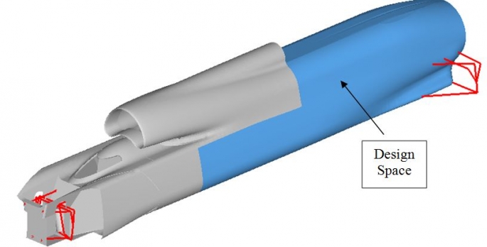
For composite structures, specific optimization techniques are used to allow each ply thickness and orientation to vary in achieving the optimum design. For non-composite structures, topology optimization is the preferred option. Topology optimization generates an optimized material distribution for a set of loads and constraints within a given design space. Manufacturing constraints can also be imposed (e.g. draw direction constraints, extrusion constraints, symmetry planes, etc).
 Optimizing a space frame means finding the most efficient pattern for the truss beams (e.g. big longitudinal beams in areas where the structure is mainly loaded in tension/compression and cross members where the shear is predominant) within a confined design space. In the OptiStruct environment this means that the user enters the package space information, design targets and constraints, as well as manufacturing process parameters, and OptiStruct then generates a design proposal that is optimized for the given design targets.
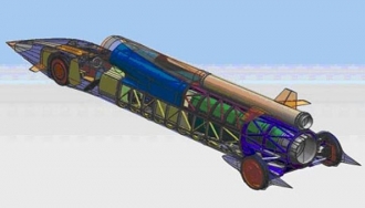
A 2D shell model of the vehicle is then built using a finer mesh to idealize the back end where the optimization takes place to ensure more accurate results. The suspensions are represented by rigid elements and spherical joints. The jet engine, rocket, MCT V12 engine, jet fuel tank and HTP tank are modelled as point masses concentrated at their centre of gravity.
The global stiffness is the main design driver for the space frame, as it alone constitutes more than 50% of the vehicle's primary structure. Only bending and torsion loadcases have been assessed. In the bending case, the vehicle is simply supported at the hub's centrelines and the load is the gravitational acceleration (1g = 9.81m/s2) applied to the 6.4 tonne mass of the car. In the torsion case, the support is on the rear wheels centrelines only and two opposite vertical forces are applied at the front wheels centrelines.
In order to set up the optimization, some design variables, a unique objective, and a set of design and manufacturing constraints need to be defined. In OptiStruct, topology optimization uses the density of each and every element within the design space as a separate design variable. The stiffnesses for the 2 loadcases (bending and torsion) are combined to generate a single parameter which can be used as an objective for the solver to maximize. Finally maximum allowed deflections of the key points of the vehicle's structure (e.g. wheels centrelines, jet and rocket mountings, etc) are set as design constraints; and max and min size for the truss beams are imposed as manufacturing constraints.
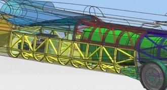
OptiStruct ran 100 iterations: at each one of them the solver took some material away from the design space by reducing the elements' density, and finally delivered an optimum solution for a space frame structure that meet all the constraints (click on the image below to play the animation). This solution can be passed on to the design team who have now a much better knowledge of where the material is more needed and therefore used more efficiently, so they can design a new set of structural beams along the optimized pattern that OptiStruct came up with. The next step in the design process will be the actual sizing of the beams (e.g. cross section geometry, thickness, etc).